For Echolink & Zello YY Voice Interface Board Controller USB Sound Card Finished
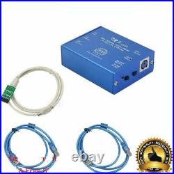
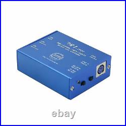
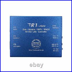

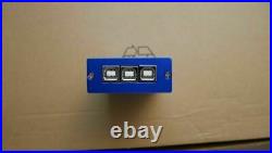
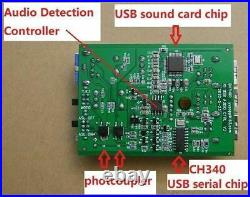
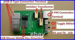
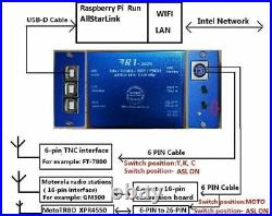
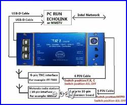
For Echolink & Zello YY Voice Interface Board Controller USB Sound Card Finished. R1-2020 Zello EchoLink SSTV PSK31 AllStarLink Radio-Network link Controller NEW. Built-in USB sound card chip, with high-quality audio input and output. Built-in USB serial chip. Launch control using RTS, receive control using DSR. The built-in audio detection chip controls the radio’s PTT button and outputs the sound to the speakers by the radio-compute-controller. The control-software forwards the input-voice of the microphone with the detection of the SQL radio signal from the USB chip(ZELLO User) 5. The USB-Radio Interface is compatible for AllstarLink. GPIO Detect COS and CTCSS input. GPIO outputs and control the PTT (ASL soundcard function). The user’s computer will not get Power/RF interference noise from the power supply from radio because the R1 has the optocouplers and the isolating transformer. R1 introduce the of electric conductor or circuit (inductance) to isolate Power/RF interference and high-frequency radiation. Full Metal case, shields all other interference. Industrial design with standard duction cess. Control Principle: In general, the Internet voice chat software, with the help of output audio controller that detects audio input from the radio PTT, hence the audio will transmit over. On the other end, once radio receive the audio, the controller detects the SQL signal through the USB control network, the voice chat software will forward to the audio to the radio. In this way, it will be on the radio-linked network. Controller Applications: By getting the radio link to the network, you can set up radio links or relay links and extend the range radio transceiver or repeater, therefor global radio link is achieved. Supported Software: AllstarLink, ECHOLINK, ZELLO, SSTV, psk31, SKYPE, QT, YY and other chat intercom and data transfer software. Notes: There are some software that not support on USB and control detection, thus at this time, while on the computer microphone input, we can use the software VOX function, or use the keyboard conversion software to trigger them. R1 external screen function description with laser engraving. “TX: RED” and “RX:B/G”: This is LED status indicators. When R1 controls an external radio, R1 lights up red. When the external radio receives the signal, R1 blue light or green light. Switch position-MOTO: Connect 6-pin to 16-pin converter board, used by Motorola radio stations16-pin interface, (Default accessories). Connect 6-pin to 26-pin converter board, used by Motorola radio stations (26-pin interface), (optional accessories). Switch position-Y, K, C: Direct connection, YAESU, Kenwood, ICOM… Radio use (6-pin TNC interface) Switch position-ASL OFF: AllStarLink is disabled, the USB sound card chip stops detecting COS / CTCSS and controlling PTT. Switch position -ASL ON: AllStarLink is enabled, USB sound card chip detects COS / CTCSS and controls PTT. Note2: “ASL ON”, Only use AllStarLink to connect with Raspberry Pi. In other states, the switch position must be in ASL OFF! DIN 6 Interface: Use 6-pin Cable. R1 to connect YAESU / Kenwood / ICOM-radio; Use 6-pin cable and “6-pin-16 pin conversion board”. R1 connect Motorola-radio; Use 6-pin cable and “6-pin-26 pin conversion board”. R1 connect MotoTRBO-radio; USB Audio: USB-Radio Interface, Connect to PC or Raspberry Pi; USB Detection: USB mouse middle button detection, connect to PC when running ZELLO or YY… USB Serial Port: USB serial port, connect to PC when running ECHOLINK / PSK31 / SSTV… About squelch (SQL) control enable, valid or invalid: YAESU, Kenwood, ICOM radio internal, the value of the SQL signal on the resistance will need to be les than 10K (max 10K), then the test will pass. If the SQL signal on the resistance value is greater than 10K (>10K), then it will not support. The use of the following schematic is for YAESU FT-7800, the SQL on the resistance number R1202 is 4.7K, which is supported by R1. When your radio’s squelch connection resistor is 47K or 100K, SQL control is invalid. If you can DIY, you can change the squelch connection resistor to 4.7K, and the SQL is valid after connecting to R1. Note 3: About YAESU, Kenwood, ICOM car radio whether to support the use of connection, if you do not understand the schematic or need any confirmation, kindly take the pictures of the HD radio schematic sent to me for confirmation DIY connection to other radio stations. PCB support DIY date May 23, 2020, all future versions support DIY 6-pin to 26-pin conversion board (connected to motoTRBO-26 pin accessory). Below is the XPR4550 physical connection: Accessories Terminal Settings by CPS: RX Audio Type: Filtered Squelch Pin #17: Ext Mic PTT Action Level: Low Pin #21: PL/Talkgroup Detect Action Level: Low “6-pin to 26-pin conversion board” supports most Motorola mobile radios with 26-pin accessory connector including but not limit to below models: XPR Series: XPR4300, XPR4350, XPR4380, XPR4500, XPR4550, XPR4580, XPR5350, XPR5550, XPR8300 XiR Series: XiRM8200, XiRM8220, XiRM8228, XiRM8620, XiRM8628, XiRM8660, XiRM8668 DGM Series: DGM4100, DGM6100 DM Series: DM3400, DM3401, DM3600, DM3601, DM4400, DM4401, DM4600, DM4601 Note 4: There is no guarantee that all versions can be used normally, please make sure that the radio version matches your region. Below is the picture of the 6-pin to 16-pin conversion board (the accessory to be connected to Motorola-16 pin). The above 6-pin to 16-pin conversion board, it is for Motorola radio and to use for connection on GM30, SM50, SM120, GM338, GM398, GM3688, GM950I Radio default setting: PIN2=MIC INPUT, PIN3=PTT, PIN7=GND, PIN8=SQL (Action Level: Low), PIN11=AF OUT Driver Installation: -USB sound card chip: the Windows operating system has the integrated driver; hence, installation is not needed. USB mouse middle key detection chip: the Windows operating system also has the integrated driver; hence, driver installation is not needed. But you need to install the USB serial driver, the download link is as below. Note 5: Regarding on this R1 appliance box, please be informed that when PC is restarted, it will become abnormal. Please power off/turn off the radio power supply first, then only restart the PC. The reason for the above blem is related to the driving control principle of the R1 and PC. There is no solution on this blem yet. For the extra info, if the R1 control encounter abnormality after the PC turned off, please set “PC shutdown=USB no power supply” in the PC BIOS. Raspberry Pi system settings Rx Voice Level Value 2 Set Rx Voice Level (using display) Value range:000-999 R1-2020, recommended values: Minimum 020 Max 111 Default 050 The actual value is confirmed by radio test. Connection to use in YY: (YY is only available in Chinese Simplified version) On the YY channel, select both the microphone input and speaker output to “USB PnP Sound Device” on the system audio management interface, please do not select microphone enhancement or AGC, if you select the option, the audio of other party will be very loud and noisy. External radio transmission is the internal default control, it does not need to set. Tip: The middle mouse button control function should be reserved for YY software. In order to avoid mis-forwarding network communications, other software can not overlaps/reuse/override the middle mouse button. The last two suggestions are to disable the voice mpt function. This is to avoid miss trigger on communication. Package List: -1 x R1 controller -2 x USB-D Cable -1 x 6 PIN Cable -1 x 6PIN-16PIN Conversion Board (6PIN-16PIN or 6PIN-26PIN conversion board, optional). We send by default: use 6-pin 16-pin conversion board. If you need to use the 6-pin 26-pin conversion board. Please write to us. E-check may not be cleared instantly. Countries that are not included can refer to its nearby country but may vary with its strictness of local custom. We will contact you if there are 2 addresses. Actual transit time varies. The following matrix is for your reference. Best to worst estimated time are offered eg. BRAND NEW: All items will be checked before packing to ensure its function. All items are new. Defective items or blems with your order must be reported within 3 days after receiving. After 3 days, exchanges will not be given. IMPORTANT: Please keep all packaging, documentation, packing list, etc. That came with your order. These will be used to verify claims if there are any blem with your order. We can’t help you if you can’t help us verify your claim, if thrown away, we’re not responsible for any claims made. This is very common for AOL & HOTMAIL users. Please CONTACT before leaving negative or neutral FEEDBACK.


Comments are closed for this entry.